CYCOGS ® Brand Holonomic Mobility Drive
The
This is the case for the
CYCOGS ®
brand of
Holonomic Mobility
using the CYCOGS ®
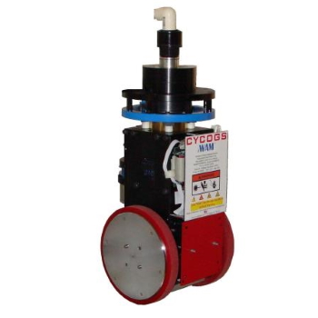
Hi2WAM™ mobility module.
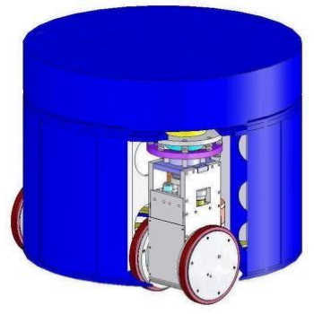
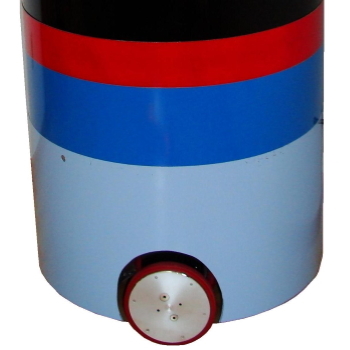
Indoor mobile robots encounter difficult navigation scenarios and collision hazards.
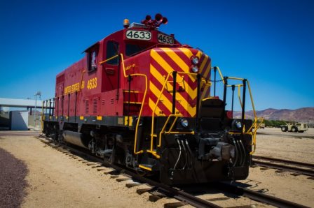
Mobile Robotics which operate on a floor or ground usually employ wheels. Holonomicity refers to robotics sum of its Degrees of Freedom (DoF) and the relationship with the Controllable Degrees of Freedom. A robot that determines all of its work space Degrees of Freedom (DoF) is said to be Holonomic. A robot or robotic part with fewer controllable DoF than total workspace DoF is said to be non holonomic, and a robot with more controllable DoF than total workspace DoF is said to be redundant. Usually, the term Holonomic is applied to robotic arms. Holonomic Redundancy usually has more DoF controllable motions than DoF available in its task or work space.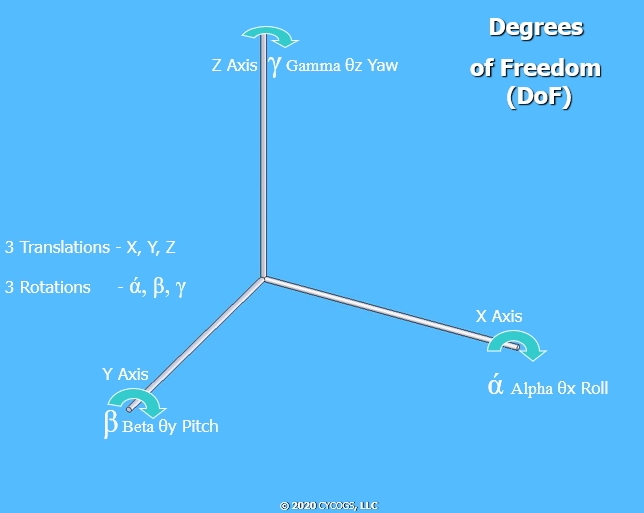 For example, a train can exclusively move on the X axis work space
(the train tracks) one - DoF and can control its position on that one axis, thus it is holonomic.
Most automobiles can be orientated and move to any position in two - Dimensional (2D) work space.
The auto requires 3-DoF to describe its position (X, Y and gamma),
but at any point, it can move only along the vehicles centerline and turn with a steering angle input.
(ignoring skidding and “drifting”) consequently, it has only two control DoF and three positional DoF; so, the automobile is non-holonomic.
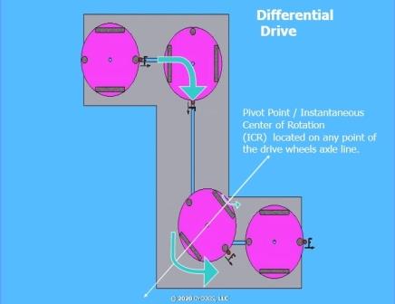
Differential Drive robots can rotate about any point located along the imaginary line drawn through the drive wheels axles,
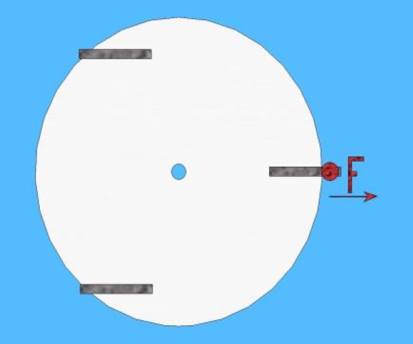
be it inside or outside the robots’ body. It uses two drive wheels, with one propulsion motor per wheel. Note the F symbol = Front of the robot. (Non-Holonomic)
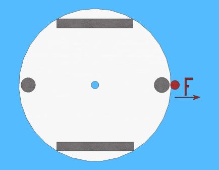
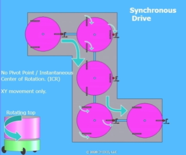
An illustration of a synchronous mobility robot movements.
Note the F = Front of the robot, it never changes direction as the robot moves. The synchronous mobility robot can only move in the X Y directions. (Non-Holonomic) If used with a docking station, any skidding, slipping or accumulated drift will create an alignment failure.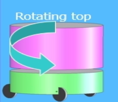
For a given task, a robot has relatively fixed parameters relating to its weight, power train and electronic efficiencies.
The robot mobility design choices can influence movement efficiencies, creating time and energy savings, which represents every engineer's goal. Design suitability, maintainability and flexibility to perform current and future tasks while is crucially important in delaying obsolescence.The choice of drive technology used in a robot is up to the robotics engineering designers, and the robots targeted end use, desired mobility and speed of travel.
With Holonomic four - DoF workspace mobility (X, Y, Z, Gamma),
the wheels can move and steer independently from each other wheel for increased maneuvering capacity, allowing the robot to rotate about any point or axis, located internally or external to its body. Many Holonomic designs use wheel offsets such as with a powered caster. Using holonomic mobility drives can offer better mobility while towing a trailer, especially when backing up. Holonomic mobility executes precise moves for operating within or around crowded spaces like elevators or hallways.With Holonomic mobility there is no need for a rotating chassis section with the associated design limitations.
Holonomic mobility allows the whole chassis rotation by the wheel assemblies if needed. The more complex maneuvers will require more software code involved to take advantage of this increased mobility. The increase in mobility capacity gives the
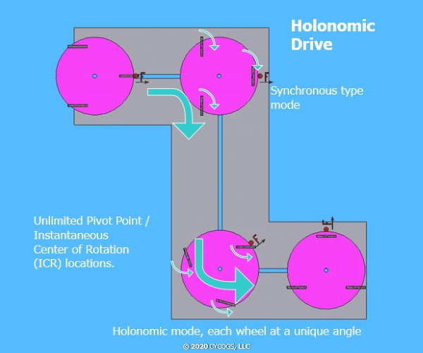
This illustration shows a holonomic three wheeled vehicle or robot. The vehicle or robot is capable of moving in any X – Y – gamma direction and or orientation. The holonomic ability allows for synchronous movements (top of illustration) and precise holonomic movements (bottom). Note how the F = Front orientation changes, as well as each wheel utilizing its own unique steering angle for a pivot point near the front of the vehicle or robot.
Holonomic Mobility Expanded
With holonomic mobility, precise positioning during navigation and enhanced movements are possible.
Now, using the holonomic mobility drives, some robotic movements are unique. One such unique holonomic movement represents the rotational translating movement, called the “Frisbee Glide.” This graphic illustrates the “Frisbee Glide”, a rotational translating movement.
The robot moves forward in the X axis direction, while rotating on its Z axis (Gamma).
The robot overall movement uses one - DoF, where the wheel assemblies are moving using 3-4 DoF.
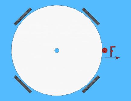
The CYCOGS ® brand Hi2WAM™ has the ability to “Park”
by rotating the wheel assemblies to point the axle centerlines to the chassis center point.
A Hi2WAM™ equipped robot can then spin in place, but not move in the X or Y directions.
This rotation ability additionally allows the robot to rotate its body to position the wheels for maximum tip over prevention.
The Hi2WAM™ when using software emulation, provides the ability to simulate other movement types besides Holonomic mobility.
These movement types include operating in Differential mode, Synchronous mode, Ackermann turns or combinations of other mobility modes plus features like a crabbing, skidding or slewing motions. This ability allows for precise moves for operating in complex and confined spaces. The benefits for a holonomic vehicle or robot include economy in movements. Spend a few milliseconds of computer time on some complex trajectory calculations, and you could save movement time or conserve energy conducting a tricky maneuver. No wasted motion.Compare this to the non-holonomic robot. Such a tricky move, if even possible for its mobility type could require several minutes of crude maneuvering to position the robot correctly. For environments requiring precise movements, implement a holonomic drive.
The Hi2WAM™ uses modularity at the Wheel Assembly level, each Wheel Assembly represents a self-contained unit.
This allows any number of Hi2WAM™ modules to be installed on a vehicle. A simple mechanical and electrical mounting easily facilitates a fast-automated hot swap of the Hi2WAM™ Wheel Assembly Modules. With the
The CYCOGS ® brand Hi2WAM™ also uses modularity at the component level.
This will enable more uptime, just repair or replace what is broken or worn out. Our modular design symmetry and redundancy can limit the
number of custom parts.
Fewer custom parts can reduce your operating costs due to economies of scale, resulting in maintenance and price savings with less inventory
to stock and maintain.
Just stock one or more sets of key spares and Field Replaceable Units (FRU) components to save on inventory
overhead and ensure your spare parts are actually purchased.
With this modularity, it is a maintenance friendly design for higher uptime and lower service issues.
Some concerns you may consider are what about the surface weight distribution?
Your floor load ratings and the robots surface weight distribution may limit its territory. We find the contact patch area damage is determined by the robots’ weight, the applied motion forces, the number of wheels, the distance between the wheels, the wheel diameter, tire width and the tire pliability/compliance. (the surface touch patch area) One remedy for the floor loading is to use wide wheels, but that results in high turn forces and floor scuffing. Another remedy is to use a larger wheel diameter allowing for an easier bump and obstacle transversal. A larger diameter wheel occupies more volume, which may not be good for your design. When using smaller wheels or rollers, they cannot easily transverse floor issues such as cracks, floor transitions and obstacles. Small wheels can also result in a bumpy ride or hang ups.
The CYCOGS ® Company solution was to include a second wheel, as in dual wheels on the wheel assembly.
Now with dual wheels, the floor loading is spread over a broader area, and it allows the wheels to rotate as they pivot, reducing floor damage.
The wheel assembly rotation axis typically would be between the wheels,
allowing a rolling motion of the two wheels. Compare this to a pivot about the wheel centerline contact patch that scuffs the floor.
The second wheel of the dual wheel assembly can be passive or actively driven.
When operating actively driven wheels, the driven wheels provide more traction and control options over other mobility options.
This illustrates the use of a single-wheel, wheel assembly and a dual-wheel, wheel assembly.


Suspension
The CYCOGS ® brand Hi2WAM™ implements a suspension, verses other wheeled drives using no suspension.
For example, a no-suspension
design is a fixed wheel position solidly bolted to the chassis and is considered a simple connection,
just bolt the wheel axle to the chassis. Much like the wheel mounting found on a cheap push lawnmower.
In the past, robot or vehicle suspension features did not directly relate to mobile robot capacity,
performance and positioning on a surface.
Currently, we recognize the ability to perform
Z axis load control and stance adjustments
can be critical for some implementations.
For instance, floor misalignment, damage or bumps could cause the robot to exhibit some rocking and tip issues.
Merely consider the detrimental effects on image processing of a vibrating, bumpy platform.
Some vehicle or robot designs may include a passive suspension. A passive suspension possesses no control over suspension movements, and the body can tilt by the terrain. Such passive suspensions are typically composed of springs, shock absorbers and fixed adjustments.
Active Control Suspension
Conventionally an active suspension supports some control over the suspension movements.
The vehicle or robot platform has controlled tilt and height adjustments. Active suspensions are typically composed of springs, shock absorbers, sensors and suspension adjustment/control motors. This is combined with load and position sensors to dynamically control the suspension adjustment motor or servos. What are the active suspension benefits?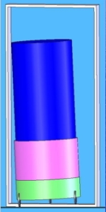
With an active suspension, the vehicle can measure the load level at each wheel assembly module.
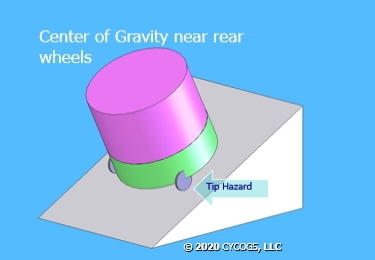
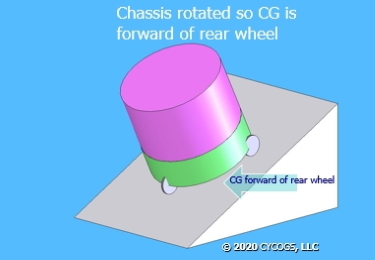
Furthermore, with active suspension, a vehicle or robot can perform a load, stance and height control using each wheel assemblies Z axis control. This allows for adjustments in floor loading weight distribution and the ability to perform Center of Gravity optimization (CG) for tip over monitoring and prevention. Plus, Z axis changes to the robots height to match the heights of an object like a table top.

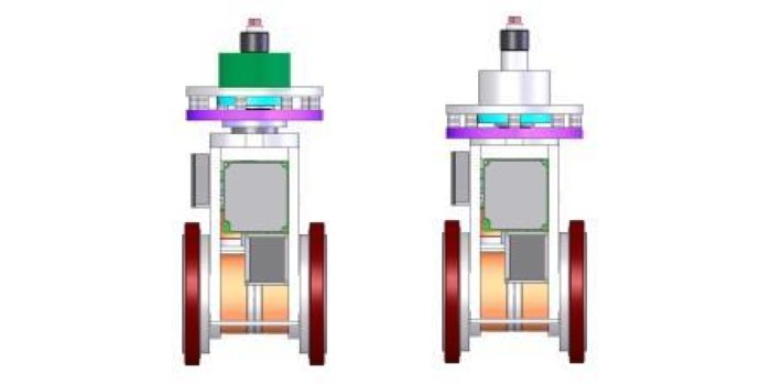 In this illustration, an active suspension robot or vehicle can control weight distribution by rotating the body and adjusting the stance
(lean)
for movement up and down inclines.
Central Intelligence Automation (CIA)
One or more central intelligent-mobility automation control computers located in the robot chassis can supervise,
direct and orchestrate multiple distributed wheel assembly modules. The central intelligent-mobility automation computer/s can collect raw or processed data and send commands or preset paths to each of the local wheel assembly modules computers. This performs high level computation for intelligent movements and synchronization, plus automating the mobility systems power management. This in effect, manages the Virtual Software Mechanisms (VSM), and is considered a Cyber-Physical System (CPS).The Embedded local wheel assembly computers provide local Intelligence and remain a part of the larger distributed automation system.
This active integration with other local wheel assembly computers as well as the central intelligent-mobility computer provides automated coordinated movements of the vehicle or robot. Granular control of the wheel assembly module data and features also operate at the local level. The local processing of command and sensor data can produce refined information and intelligent counter-commands with minimal traffic. Using the local wheel assembly module computers can enhance online error detection and fault tolerance. TheVirtual Software Mechanisms (VSM)
The CYCOGS ® brand Hi2WAM™ in operation is considered a
Virtual Software Mechanisms (VSM) and a Cyber-Physical System (CPS).
Using simulated mechanical components and linkages which are virtually simulated in software using the wheel assembly’s hardware,
computers and software,
the Hi2WAM™ has the ability to simulate
other mobility drive types such as the Ackermann, Differential and Synchronous drives.
Plus, some ability to induce slippage per wheel in an over or under speed mode.
(such as carpet rollup reduction)
Note: While the Hi2WAM™ does not possess any mechanical braking mechanisms.
Braking speed reduction is performed using regenerative braking,
and electronically a parking hold state is possible.
A power off or safe state parking brake mode can be created by rotating the wheel assemblies’ centerlines at each other,
or more compactly, in a circle.
In the circle Hi2WAM™ parking orientation, the vehicle or robot could rotate about its axis,
but no movement in the X or Y axis unless skidding or slippage occurs.
Software Control
For basic control of the vehicle or robot using the CYCOGS ® brand Hi2WAM’s, basic mobility
can be accomplished by operating in the synchronous mode.
In this mode, only vehicle velocity, and steering direction values are needed, and minimal data transfer would be needed.
Movement commands can be dumped from a main robot computer for crude maneuvers,
or sent to a dedicated intelligent central mobility computer for complex coordinated automated maneuvers.
This will depend on your mobility requirements and local computing power.
For most holonomic movements that have a variable axis of rotation, computations are used to determine the instantaneous center of rotation.
For a given path, the intelligent-mobility computer uses its navigation data and a limited world view of position
and layout to determine and automate individual wheel assembly module commands.
The local wheel assembly computer determines unique values for each wheel, steering and height adjustment motor.
The use of a load cell allows for load measurements that can be used to control the suspension for height or load control.
The benefits accumulate for a holonomic robot, including economy in movements.
Spending a few milliseconds on complex trajectory calculations for a tricky energy conserving maneuver saving real time and energy.
Compare that to a similar maneuver for the non-holonomic robot,
and it could require several minutes of crude maneuvering to position the robot correctly, if it was even able to.
What is possible when you combine these features?
You have an intelligent modular holonomic wheel assembly using dual, independently controlled wheels with an active suspension system. This is the


Mobility Examples
Using the

 In this illustration, a docking example shows how the robot pivots and angles its movements to align with
docking port connector.
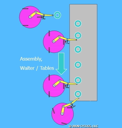
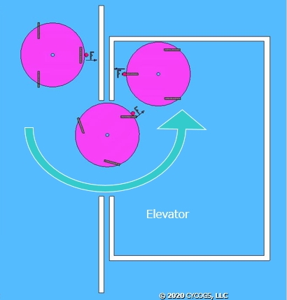
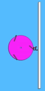
This illustration presents two examples of enhanced holonomic movements. On the left is an example of approaching a table, a robot arm interacting with the table, and its movements following the table end. Note: F = Front of the robot. On the right is the example of moving along a wall, and rotating into an elevator or room, changing its F = Front orientation by 180 degrees.

 For further details on the
 For a story about the


Learn more about AI Robotics with the
Contact: Send questions and comments about this web site to the