What is an Emergency Stop System?
Emergency Stop Safety Systems can be comprised of an automated system, a remote system and a manually operated systems.
A manually operated emergency stop or E-Stop is a device or system to stop and interrupt system power for shutting down an operating system and / or vehicle-system electronics. (ceasing activity) This is sometimes dubbed the "Kill Switch", as it abruptly stops the system quickly, not a graceful shutdown.The most basic parts of an E-Stop system are the power supply, a load and an On / Off switch or connection. Most manual On/OFF switches do not work effectively in an emergency situation, where access, ease of use and time is critical. A properly placed, safety approved and recognized E-Stop mushroom switch remains a key part of the system. If you cannot find the switch or switches, or do not recognize the switches function, it’s useless.
Once actuated, the switch must remain in the “OFF” state until reset by a key or a switch reset action. The switch must be large enough to easily find and push, but not too small making it hard to locate on a larger vehicle or systems. For some low power systems, the E-Stop switch itself is all that is required. Larger systems will involve relay like devices to handle the higher power levels. Some systems may need energy efficient relays, others may need power disconnects.
Note:
You as the end user or OEM, must insure the proper operation, maintenance, instruction and configuration.
Placing the emergency control shutoff switch in a poor location will yield unfortunate results. An emergency switch not actuated (pressed) in an emergency is useless. The owners and end users must assume full responsibility and liability for the safe usage and operation of emergency safety switch systems. For example, if your system doubles its power input or output load capacity or capability, the emergency safety switch systems must be sized correctly and updated also.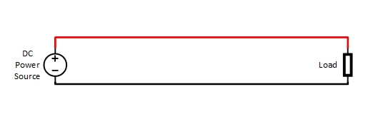
A basic circuit. Power and a Load.
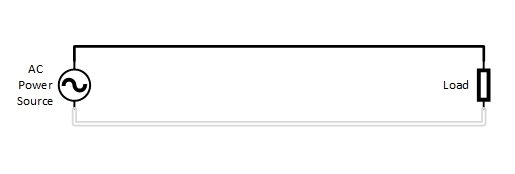
A basic circuit. Alternating Current (AC) Power and a Load.
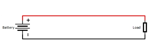
A basic circuit. Direct Current (DC - Battery) Power and a Load.
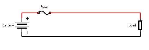
We can expand the circuit above to make it safe, by adding a fuse. This prevents a fault or short or excessive load power use from damaging the system, its components and wires.
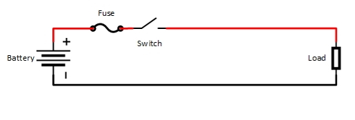
We can expand the circuit above some more by adding a switch to turn it on or off.
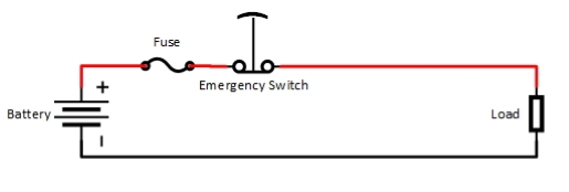
We can make this circuit above more user friendly by using an Emergency Stop switch to turn it on or off. This typically is a large, color coded push button switch that locks in the "Off" position. The underlying idea is to use a large, visible switch that you must actuate in an emergency and know the switch will remain off until its manually reset.
Liability Disclaimer:
The
For more information on the